Carrying out the check of continuity in a long wire is one of the easiest electrical tests you can perform but before testing the first thing you should do is to turn off the power supplying the wire you are working on it is an important safety tip you shouldn t ignore.
Cable continuity test format.
Screens shall be checked as common conductors.
Installation test report.
By web master march 17 2015.
Glands shrounds earthing bending termination core earth core core core screen core armr screen armr cores screen armr earth sys test volts test equipment.
Wire map basic continuity test of connectors onto a cable.
Low insulation of cable leads to inadvertent energisation or de energisation of circuits.
Continuity insulation signed notes.
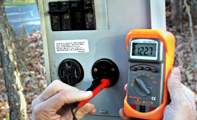
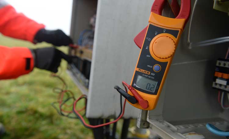
You would need a device called the multimeter with a multimeter you can test for current voltage and resistance in.
From simple two wire cables to custom cable assemblies and complex wires harnesses shine uses electrical testers made by cirris systems to ensure reliability and performance.
Continuity insulation resistance testing report.
The meggering should be carried out at initial stages before and after cable laying.
But for detecting and testing for a leakage current during a normal or overloaded condition a special instrument known as the insulation tester is used.
For maintenance purposes these tests shall be performed periodically.
Power through a network cable to power small devices like phones wireless access points and cameras.
After test results are approved for new cable and the splice is completed an insulation resistance test and a shield continuity test shall be performed on the length of new and existing cable including the splice.
Doc ref no.
How megger testing is performed.
2 wires for resistances 1 ω and 4 wires for resistances 1 ω.
During testing all cables and wiring must be completely disconnected from any equipment.
Test results general checks insulation tests mω continuity tests cable no.
Test cores and record the lowes value remarks.
The continuity test can be made in 2 or 4 wires according to the resistance to be measured.
Each core to ground continuity point to wire check with low voltage tester check correct installation of cable glands.
The continuity test also called low resistance measurement is measuring the low resistance of cables from 1 mω to 250 ω.
Between signal wires 2.
Meggering of signalling cable is done to test the continuity and insulation of the cable conductors.
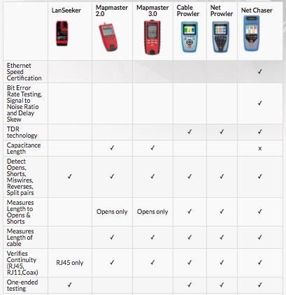
Checks for opens shorts miswires and split pairs.
After a satisfactory insulation resistance test a test in accordance with the types listed in section 7 3 3 2 4 may be.


